Archive for the ‘Pumps’ Category

DDC3.2 Pump Heat Scoping

Posted: May 30, 2011 in Pumps

If you have owned a DDC series pump (particularly one of the 18W flavors) you’ll know that they tend to get hot to the touch on their bases. In preparation for some evaluation of cooling options on DDC series pumps, I wanted to explore “Where” the heat is coming from in more detail.  I needed to install at least one temperature probe, so my question was where?

To run the pump bare with the PCB exposed,  I used some hardware (Standoffs+washers) to mount my XSPC V1 DDC top to a Laing DDC 3.2 that I’ve had in my inventory.  I have noticed a higher power consumption from the 3.2 vs the newer 3.25 model, so I figure it would make a good worst case / high heat test subject.   Measuring the exposed PCB would allow me to see exactly what was creating the heat and have a better sense of where I should place thermal sensors for future cooling tests.

For temperature measurement, I used my Raytek Minitemp Laser thermometer to shoot and scan over the PCB of the pump bottom.  It’s not very high in precision, but it is an easy means to scan and measure a large number of surfaces very quickly and find the problem areas.

I also initially set the restriction level on my valved flow meter to 2.0GPM to represent a higher flow/lower restriction condition which has been shown to draw more power from the pump.
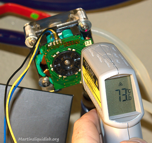
Here you can see the approximate measurement methods used with the laser thermometer.

And after scanning over the entire surface, this is the approximate temperature grid I was able to measure @ 2GPM:
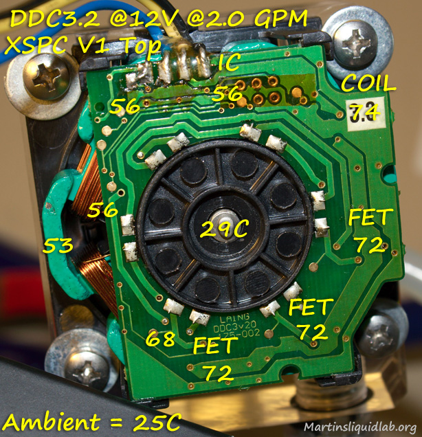
Center of pump is cool relative to the FET and Coil areas on the right.

Restriction/Flow Rate Influence

While I picked 2 GPM as my mark of lower restriction, I did notice fairly dramatic changes in temperature with differing flow rates and explored that a bit.  I was fairly surprised at how temperatures rise with increased flow rate.  From pump testing, I was able to see this at a smaller scale via power consumption numbers, but temperatures are more dramatic.

Here are a couple of pictures of the temperature exploration at 3GPM:

Measuring at 3GPM shows a dramatic increase in temperature.
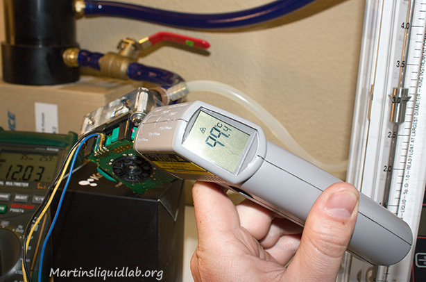
Coil Temp nearly 100C! @ 3GPM

While this isn’t of any high precision or accuracy, this is an approximate relation of the FET area PCB temperature relative to flow rate with the pump casing removed.
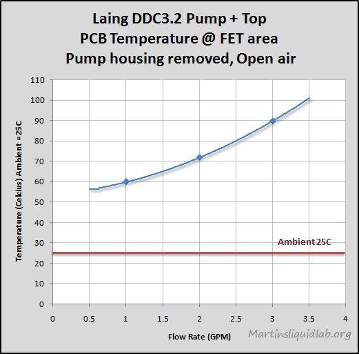
FET temperature is very dependent on flow rate.

Low Restriction + Full DDC3.2 Pump Power + Pump Top =  High Heat

Links to DDC’s melting down

I thought the following is a good example of the extreme heat causing problems for some folks:

http://forum.hardware.fr/hfr/OverclockingCoolingModding/Water-Xtreme-Cooling/pompe-laing-prend-sujet_277053_1.htm

Conclusion

It appears the FETs and coils run the hottest on the pump and the IC is of little interest.  Also the center of the pump base is not very representative of the hottest areas.  I will see what I can do about placing a probe or two near the FETs and coil area inside the pump casing.  A high restriction system at 1GPM only measured roughly a temperature of Ambient +35C while the very low restriction 3GPM condition resulted in almost twice the delta of Ambient +55C.  I’m beginning to think heat removal via a heatsink is more important than most people think when running DDC pumps with tops.  The factory Laing top will restrict that max flow rate, but once opened up via a pump top…the heat is ON!

This is a bit preliminary, but it may also make more sense to design a balanced system of pumping power vs restriction.  Too little restriction under full power is apparently making these DDC pumps with tops heat up, while too much and you could have bleeding problems and reduced thermal performance.  Shooting for 1-1.5GPM or so with DDC pumps, may be a good target to keep heat in check.

More testing to come….I will be exploring heatsinks and air flow scenarios soon.  I just need to find some fine wire to solder a few probes inside my DDC for testing enclosed.

Cheers!
Martin
Water cooling enthusiasts routinely seek options away from the standard.  They want improvements to performance, better looks, and options. The PMP-400 (DDC 3.25) pump comes with a factory 3/8″ plastic barb top.  While this works just fine for 3/8″ tubing systems, it’s not very convenient for larger tubing users and it’s not nearly as appealing as a threaded top that can accept your favorite shiny barbs or compression fittings.

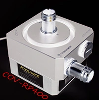
Welcome to my review of the Koolance COV-RP400 Acetal DDC Pump Top, the BDY-TK200 60x200mm Acrylic Tube Reservoir, and the COV-TKTOP acetal reservoir tope for the PMP-400 (DDC 3.25) series pumps. Koolance has a very modular system of parts and accessories to build a variety of pump/reservoir  combined or separated systems.   You basically pick and chose the various pieces and build your own creation. I requested several review samples for my pump noise testing and found the top to do exceptionally well there and wanted to supplement that work by doing some pump PQ test comparisons.

A special thanks to Tim from Koolance for sponsoring the parts used in this review.

Packaging & Accessories Information

I missed my box opening photo opportunity and have been using this pump in various noise related tests already, so I won’t be doing my usual here. The package was done very well in Koolance’s typical black box with ample protection.  It comes with a heavy duty fan mounting bracket , the pump top, a port plug, and necessary mounting screws. The only thing missing is a set of barbs (Nozzles) which you’ll have to purchase separately.

You can see some more on the accessories at Koolance’s site here.

http://www.koolance.com/water-cooling/product_info.php?product_id=980

Noise

Moving onto the pump top itself, it is an extra thick acetal top which has shown to be the best noise reducing DDC top tested so far.  Because the top is modular and capable of accepting a reservoir, the top thickness is an unusually thick 26mm of acetal goodness.  I suspect this is the primary reason it does so well in noise reduction.  Acetal is better than acrylic at reducing noise and the thicker the better.  Here is another copy of that video:

Pump Volute

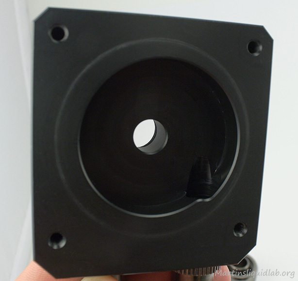
Here is a quick look at the pump volute.  It does have a reduced inlet port size which is good in matching the impeller inlet size.  The exit port is not quite as refined as some others I’ve seen.  The volute perimeter is also more a semi spiral than a complete ever increasing radius spiral shape.

While most veteran water coolers have come to accept that pumps in series is the preferred through practice, occasionally the question of series vs. parallel comes up in forum discussions.  There is quite a bit of good information out there in this regard for industrial pumps, yet I haven’t seen much documented on this question with actual testing in water cooling.  In an effort to provide another resource and to provide some testing to support theory and practice, I decided to test just that.  I proceeded to test two pumps in series and parallel and also evaluate the redundancy result if one pump stops for safety purposes.

Before going to far, I would like to thank my many sponsors including Koolance, XSPC, DIYINHK, and Bmaverick for the pumps and mods used in this evaluation.

DIYINHK

Bmaverick

To test and evaluate performances, I used conventional methods of testing dynamic head pressure vs flow rate each scenario.  This evaluates not only one restriction condition, but the entire range of conditions possible for a very complete look at pumping performance.  I utilized a Dwyer 477-5 digital manometer for pressure differential and King Instruments 7520 0-5gpm flow meter.  For voltage I used a Cen-tech P98674 measuring at the pump plug, and for amperage I used my Mastech HY3005D power supply amperage meter.  In this round I skipped the RPM monitoring due to the use of two different pumps.

Note: This test is for PUMPS ONLY!  Parallel vs. Series LOOPS is a whole different topic and I’m not testing that here.

There can be some benefit to parallel LOOPS under the right desired condition, but I wanted to look at pump setups under this test.  THIS IS PUMPS, NOT LOOPS..  Many people for example run multiple like GPU blocks in parallel to reduce the restriction caused by the GPU blocks and emphasize more of their pumping power on the CPU block. Nothing wrong with that, but that’s parallel “LOOPS”, and this test is “PUMPS” only, make sure you understand the difference.

SINGLE PUMP TESTS

I purposely chose to use two different pumps for a couple of reasons.  For starters, there is a “forum myth”, that you need to match two like pumps when run in the same loop.  I believe this grows from an assumption that the impeller speeds need to match and also because of the fear that one stronger pump would “Push” the weaker pump beyond it’s abilities.  Fortunately, this myth is wrong. As long as the net system flow rate does not exceed either one of the pump’s operating range, there is no problem at all with mixing different pumps.  Actually, I would recommend it over two of the same because they have different noise frequencies.  Due to this difference in noise output, the combined mixture of noise is smoother than putting two exact pumps together.  In addition, I have experienced RPM harmonics between two like pumps where if the RPMs are extremely close, but just slightly off..you can get an undulating harmonic noise effect that can be very harsh.

I also chose two different pumps so I could more closely examine the result of pumps in series and parallel vs the single pump results.  In the end, the two mixed pumps worked perfectly together, and the test results using two different pumps did find some interesting details out for me particularly the parallel test results.

Moving on, here are the individual pump curves previously tested:

PMP-450 Detail

DDC-1 Tested at 12V

DDC-1 Detail

Testing Pumps In Parallel

To connect the two pumps in parallel, I used some custom Y fittings fabricated out of copper 1/2″ pipe.  I made these myself to represent the best possible condition for parallel.  Actual usage with more conventional Y fittings would perform slightly worse than what was tested because of the added restriction.  You can see the setup below:

Parallel Testing In Progress

Parallel Detail

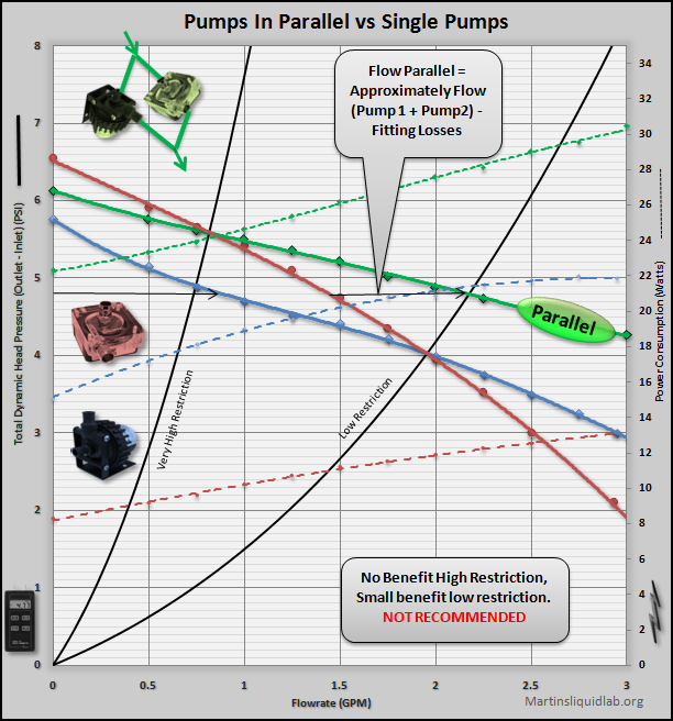
Only small gains for low restriction setups, NOT RECOMMEND!

The result was somewhat as expected (Very Poor), but there are some interesting oddities.  When you run two pumps in parallel, the curves somewhat get stacked in the X or flow rate direction with an averaging of pressure.  Unfortunately this means the real gains of parallel don’t happen until you get beyond the useful restriction range of water cooling loops.  On a very high restriction loop you actually don’t gain anything at all.  The parallel curve crosses the single DDC curve at about the same point.  On a low restriction setup you would see some gains, roughly a 22% increase in pressure, but not at all what you might have hoped for.  Parallel simply doesn’t show benefits for the higher restriction levels that we typically see in water cooling and that holds true for pretty much any typical water cooling pump.

As you can see, it really doesn’t matter much which pump, the result simply doesn’t favor parallel pumps.

Beside the expected poor results, it was interesting that the parallel result is not simply adding the X direction as I thought.  Max head pressure for example is not the 6.5PSI of the DDC, instead it is an average of the two pumps(6.1PSI).  In the end it’s more complex than just adding the X direction, but the bottom line is that it’s not good and definitely not recommended. Parallel pump performance is poor for water cooling.

Parallel Pumps Redundancy Check

Besides performance, many folks use two pumps for redundancy purposes.  On occasion, pumps do fail and the idea is that if one fails, you’ll still have one moving adequate water for cooling.  Parallel is a bit unique and has raised quite a number of debates amongst forum members about this exact item.

What happens in parallel when one pump fails or quits for whatever reason?

To test this, I simply disconnected the PMP-450 and retested the parallel configuration.

Parallel One Pump Off Detail

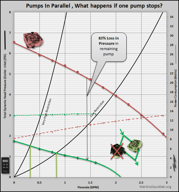
DDC Single pump vs in a parallel setup with second pump off

Rather than the DDC pump pushing through the intended loop, it is now bypassing that intended loop via the PMP-450 subloop.  That’s bad new for parallel loops, as you lose not only the one pump that quit, but you also loose about 83% of the remaining pump’s power.

However….it does still have “Some” pumping power left over.  While it’s not going to be of any good levels, chances are your loop will still get between .3GPM and .8GPM which will function without causing catastrophic failure.  In the end…it will still serve a redundancy benefit..but barely.

Elbow effects on pump performance

Posted: April 23, 2011 in Pumps

So we have looked at elbow restriction impacts before, but not in close proxity to the pump. We have seen that replacing the factory elbow inclusive DDC top with one that is aftermarket provides significant performance improvements, yes there is still a need for them in certain installations. This article is devoted to exploring the effects of elbows and port alternatives of the DDC pump.

A special thanks to my sponsors:

ENERGY LOSSES

Normally an elbow in the system is nothing more than friction or pressure drop. It is relatively small and for most users ignored if only a few are used. However, elbows are more important at the pump because the cause both restriction and ditsturb the flow within the conduit. Undisturbed flow within a long piece of tubing has a very even conical shaped velocity profile where the velocity is highest away from the walls at the center if the tube. The introduction of an elbow however disturbs that. The result is you get more flow off to one side. At the inlet of a pump this means the impeller is loaded slightly off balance and causes a loss of efficiency. How much loss likely depends on how close the elbow is to the impeller, how sharp a bend it is, and how small the ID.

Another potential problem with elbows at pump inlets has to do with cavitation. Pumps create a “differential” pressure which means a negative pressure at the pump inlet and posotive at the pump outlet. Negative pressure if strong enough can cause water to boil at room temperature. You might recall such an experiment in high school chemistry where using a vacuum chamber caused water to boil. This is what causes cavitation. In a pump however it only appears in the form of noise because the pressure increases very dramatically as it passes the impeller. You get a bacon sizzle type noise which is air bubbles forming that almost instantaneousouly form and collapse back to a fluid. Cavitation is of high concern in large industrial pumps because it can cause corrosion of the impeller. In water cooling, it more of an issue of causing unwanted noise and possibly some loss in efficiency. I have yet to see a worn impeller myself and have typically only witnessed cavitation in testing under extremely high flow and low restriction conditions that are not normally found in real world systems.

So..we have restriction losses which are fairly small, impeller loading losses which can be significant, and possible cavitation issues assocoated to pumps with elbows. To explore this, I figured on the normal PQ curve testing and simply add elbows or change ports and see what the results are…

TOPS WITH ALTERNATE PORT OPTIONS

My first look is using th Koolance COV-RP400 and Koolance PMP-400 (DDC 3:25) pump top. Some tops offer what I would call “Internal Elbows”, which allows the user to modify the port orientation using supplied port plugs and simply installing the barbs in the preferred orientation and there is no need for additional elbow fittings.

First, let us have a look at the factory top. The top is designed with XXmm ID ports, the outlet is tangential and in plane to the impeller, however the inlet includes a small ID 90 elbow integrated into the top. It is radiused, but the ID is small and very close to the impeller.

This is the second in the PCB mod options from DIYINHK, the Sanyo 10W version. Who doesn’t like the idea of modifying one or repairing an old broken pump and this one focuses on silent operations.  Wizard1238 posted the information about his DIY kits on xtremesystems here and it quickly caught my interest.

A special thanks to wizzard1238 at DIYINHK, check out his Ebay store for DDC mods and projects.

Pictures and Information

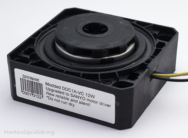
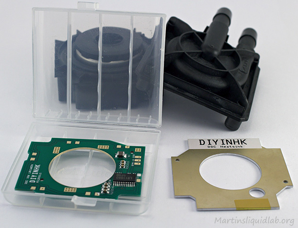
First a few pictures of the Sanyo PCB mod installed on a Laing DDC1 pump with black rotor.

Black rotor DDC-1 was already modified with the Sanyo motor driver

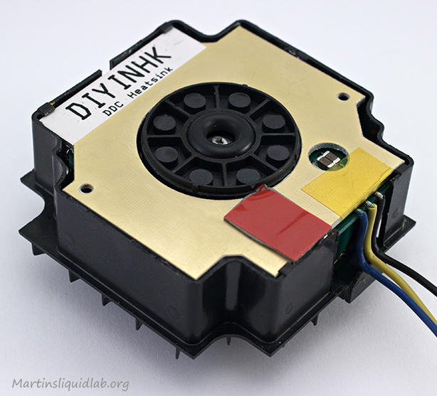
Heatsink PCB fits inside nicely

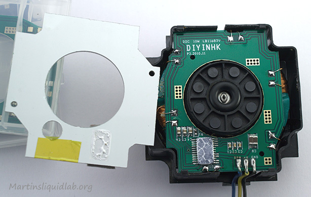
Pulling out the heat sink reveals the assembly and Sanyo, TIM on Sanyo for heat transfer to heatsink

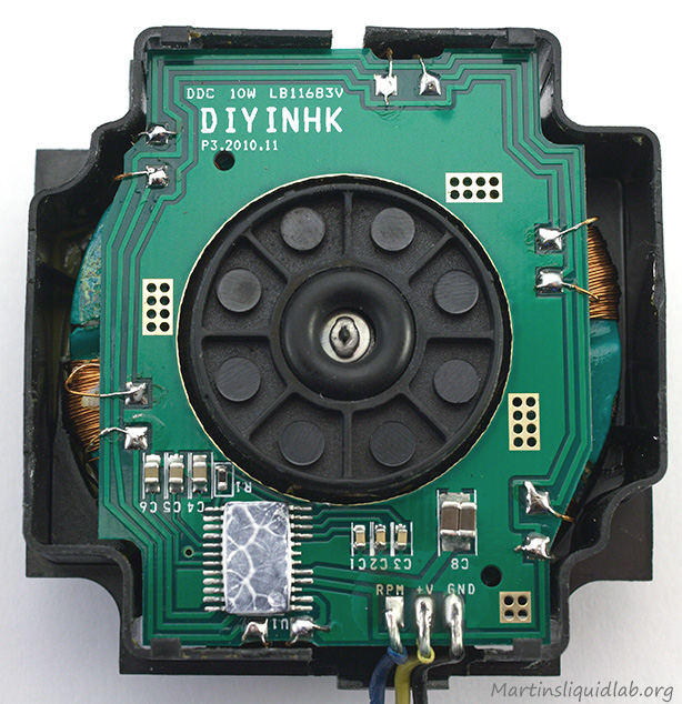
Closer look at the PCB installed

Ready for a soldering project...

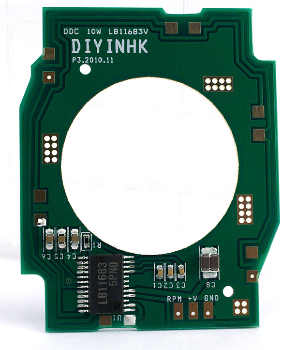
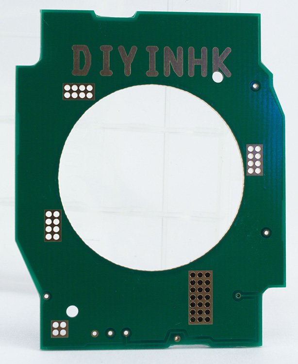
PCB side facing the pump bottom and close up of Sanyo motor controller

PCB side facing pump top

Sanyo LB11683V Motor Controller Info

I did some searching for information on this particular motor controller and found Sanyo’s site with additional detail:

Sanyo Site

Sanyo LB11683V PCB Product Sheet Download <– Good technical document

Of particular interest some following highlights:

  • Quiet Operation (Current soft switching circuit)
  • Built-in thermal shutdown operating temperature 150-210C
  • Voltage rating 7.0V – 13.8V (Vcc max=14.5V)
  • Current max – 1.5 Amps
  • Allowable power dissipation – .5W
  • Operating temperature -30 to 85C
It also has a little graph showing a relationship between power dissipation to ambient temperature being .5W from -30 to about 25C, then tapering down to .26W at 85C.  I’m not quite sure what this chart represents in terms of temperature throttling or if it’s simply indicating how much heat the bare IC can dissipate.  In my test, I had the heat sink PCB installed and didn’t notice any reduction in power or throttling.  The thermal shutdown temperature is very high, so I have a hard time seeing where you would get that hot.
I would highly recommend the heat sink PCB be installed, it fits inside the casing and helps distribute heat, so it’s a really good benefit to helping distribute heat.

Testing

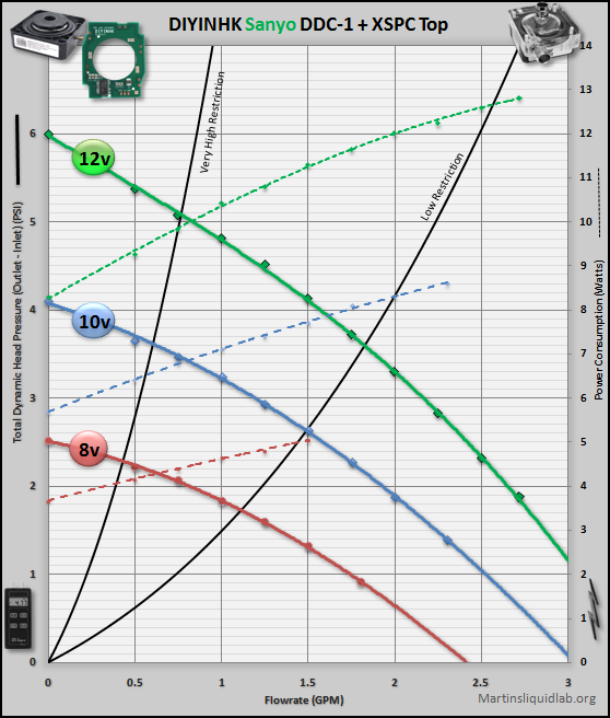
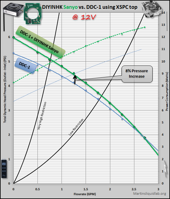
I followed my usual dynamic head pressure vs flow rate pump testing.  The pump performed very similar to the DDC-1 curve at 12V, but at a reduced noise level and slight bump in performance:

8V Detail

10V Detail

12V Detail

Voltage Run = Good Broad Range Scaled by Volts

DDC-1 Comparison

So nothing dramatically more powerful like the Toshiba controller on a DDC3 pump, but the Sanyo does provide a small boost of performance over a DDC-1 pump.  I’m a bit of a noiseless fanatic myself, so I was very happy with the performance. A high to low restriction system will still have plenty of power to maintain over 1GPM with just a single pump.  If you need more, you could always put two in series and double your pressure..:)

Noise

Noise is always very subjective, and hence I generally lean toward using a video method while utilizing a fixed gain stereo microphone.  I have a Zoom H1 set at 100% manual gain that is mounted to my Canon T2i that works pretty well.  It has a nice flat frequency response, so if listened to with quality audio gear, I think gives a pretty good representation of the actual thing.  Not perfect, but about as good as I’ve figured out how to do.  In addition I normally include my A-weighted sound level meter for reference.

Here is a video of the PCB inside a DDC-1 along with some back to back recordings with a factory Laing DDC-1 and Laing DDC3.2.

Installation Notes & Video

I’ve now gone through and installed both PCBs each in DDC-1 pumps with success, although it does take some time and patience.  I would highly recommend that you have a tub of flux, and find some fine pointy tweezers.  I tried to do it without tweezers and struggled because of that.  Another tip is to spend extra time making sure you don’t break any of the wires.  One pump I managed to salvage all but one wire and life was pretty good. Soldering the wire back in place is relatively easy since the end of the copper wire is pretinned.  However when you have to extend the wires, it takes extra time tinning and cleaning the end of the enamel covered coil wire.  In addition a short splice can mean when you heat the wire for PCB soldering that you could accidentally unsolder your splice. Finally I think it’s fairly critical that any splices do not touch the coil or any metal part.  The OEM coil wire is covered and protected by the enamel, but once you splice, you lose that.  Any splices or bare wire should be heat shrink protected to prevent grounding on the coil or magnets.

With all that said, I attempted to create my first installation video.  I really should have done one of these pumps before recording as to avoid the many mistakes…but I only had one Sanyo PCB, so I recording my first experience with this.

I would also like to thank Bmaverick for sending over the deceased pump to do this mod on.  If you haven’t seen it, he has a lot full of new old stock DDC-1’s for sale that could either be run as is, or modified with either the Sanyo or Toshiba DIYINHK controller.

Conclusion

I really enjoyed the Sanyo controller PCB mod.  It gives a small boost to performance and also improves noise levels on the DDC-1 series pumps.  More power, less noise…very nice!

PROS

  • An excellent way to revive an old pump
  • Small boost to performance on the DDC-1 (8% pressure gain)
  • Improvement to noise quality on DDC-1 pumps
  • Heat limiter to protect pump
  • I/C controller is inverted allowing installation of the heat sink PCB for good heat dissipation
  • RPM readout appears to be accurate (pulses are the same as a normal fan)

CONS

  • DIY difficulty is higher than average.  Suggest to those with patience and fine soldering skills.
Cheers!
Martin
Where to buy