This is the second in the PCB mod options from DIYINHK, the Sanyo 10W version. Who doesn’t like the idea of modifying one or repairing an old broken pump and this one focuses on silent operations. Wizard1238 posted the information about his DIY kits on xtremesystems here and it quickly caught my interest.
A special thanks to wizzard1238 at DIYINHK, check out his Ebay store for DDC mods and projects.
Pictures and Information
First a few pictures of the Sanyo PCB mod installed on a Laing DDC1 pump with black rotor.
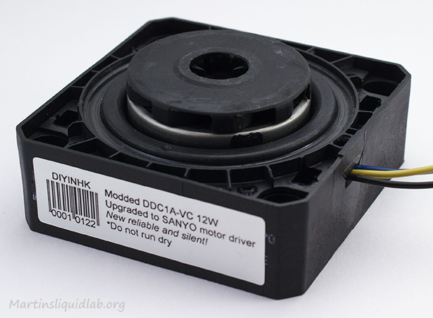
Black rotor DDC-1 was already modified with the Sanyo motor driver
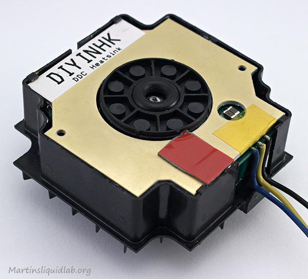
Heatsink PCB fits inside nicely
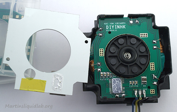
Pulling out the heat sink reveals the assembly and Sanyo, TIM on Sanyo for heat transfer to heatsink
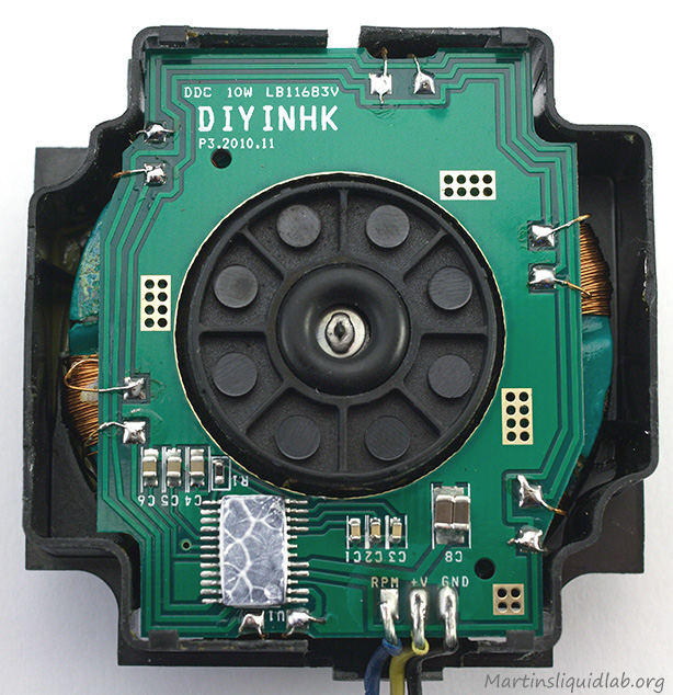
Closer look at the PCB installed
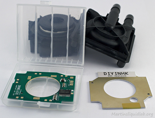
Ready for a soldering project...
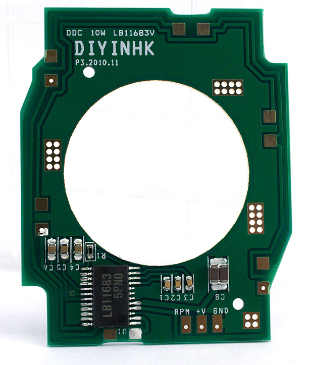
PCB side facing the pump bottom and close up of Sanyo motor controller
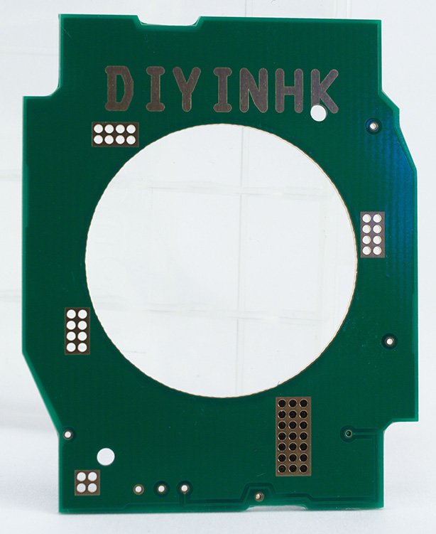
PCB side facing pump top
Sanyo LB11683V Motor Controller Info
I did some searching for information on this particular motor controller and found Sanyo’s site with additional detail:
Sanyo LB11683V PCB Product Sheet Download <– Good technical document
Of particular interest some following highlights:
- Quiet Operation (Current soft switching circuit)
- Built-in thermal shutdown operating temperature 150-210C
- Voltage rating 7.0V – 13.8V (Vcc max=14.5V)
- Current max – 1.5 Amps
- Allowable power dissipation – .5W
- Operating temperature -30 to 85C
Testing
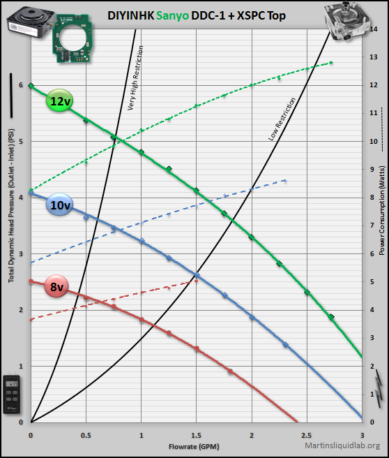
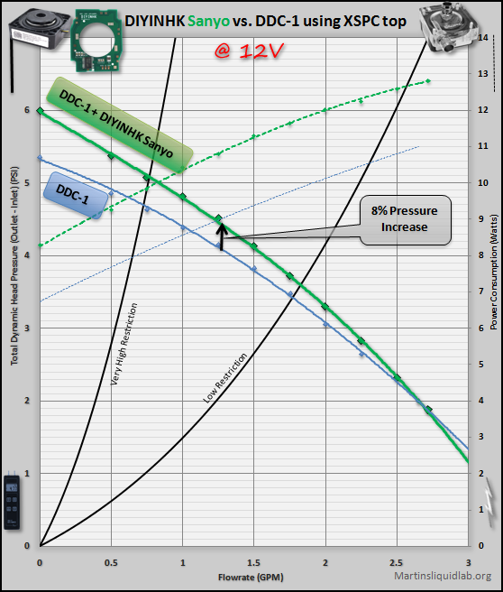
Voltage Run = Good Broad Range Scaled by Volts
DDC-1 Comparison
So nothing dramatically more powerful like the Toshiba controller on a DDC3 pump, but the Sanyo does provide a small boost of performance over a DDC-1 pump. I’m a bit of a noiseless fanatic myself, so I was very happy with the performance. A high to low restriction system will still have plenty of power to maintain over 1GPM with just a single pump. If you need more, you could always put two in series and double your pressure..:)
Noise
Noise is always very subjective, and hence I generally lean toward using a video method while utilizing a fixed gain stereo microphone. I have a Zoom H1 set at 100% manual gain that is mounted to my Canon T2i that works pretty well. It has a nice flat frequency response, so if listened to with quality audio gear, I think gives a pretty good representation of the actual thing. Not perfect, but about as good as I’ve figured out how to do. In addition I normally include my A-weighted sound level meter for reference.
Here is a video of the PCB inside a DDC-1 along with some back to back recordings with a factory Laing DDC-1 and Laing DDC3.2.
Installation Notes & Video
I’ve now gone through and installed both PCBs each in DDC-1 pumps with success, although it does take some time and patience. I would highly recommend that you have a tub of flux, and find some fine pointy tweezers. I tried to do it without tweezers and struggled because of that. Another tip is to spend extra time making sure you don’t break any of the wires. One pump I managed to salvage all but one wire and life was pretty good. Soldering the wire back in place is relatively easy since the end of the copper wire is pretinned. However when you have to extend the wires, it takes extra time tinning and cleaning the end of the enamel covered coil wire. In addition a short splice can mean when you heat the wire for PCB soldering that you could accidentally unsolder your splice. Finally I think it’s fairly critical that any splices do not touch the coil or any metal part. The OEM coil wire is covered and protected by the enamel, but once you splice, you lose that. Any splices or bare wire should be heat shrink protected to prevent grounding on the coil or magnets.
With all that said, I attempted to create my first installation video. I really should have done one of these pumps before recording as to avoid the many mistakes…but I only had one Sanyo PCB, so I recording my first experience with this.
I would also like to thank Bmaverick for sending over the deceased pump to do this mod on. If you haven’t seen it, he has a lot full of new old stock DDC-1’s for sale that could either be run as is, or modified with either the Sanyo or Toshiba DIYINHK controller.
Conclusion
I really enjoyed the Sanyo controller PCB mod. It gives a small boost to performance and also improves noise levels on the DDC-1 series pumps. More power, less noise…very nice!
PROS
- An excellent way to revive an old pump
- Small boost to performance on the DDC-1 (8% pressure gain)
- Improvement to noise quality on DDC-1 pumps
- Heat limiter to protect pump
- I/C controller is inverted allowing installation of the heat sink PCB for good heat dissipation
- RPM readout appears to be accurate (pulses are the same as a normal fan)
CONS
- DIY difficulty is higher than average. Suggest to those with patience and fine soldering skills.
Martin


Actually looks like a fun mod to do and a nice way to breathe some new life into an old standard…especially if its off warranty.
Great video! I’ve played it three times already. 🙂
OK, I’m a semi-noob in the soldering skills. What fine point solder tool did you use and can you give a brand name along where to buy one? My small tools have the bent pointer dental style tool and a few other little micro pliers. When working on this job, was it done under a lighted magnifier too?
That one solder area around the new IC location looks a bit hard, but not impossible.
Thanks for the demonstration and work shown here. 🙂
BMaverick
Thanks!
I just have one of these no name brand variable irons from ebay:
http://cgi.ebay.com/Variable-Temperature-Soldering-Iron-Station-Kit-NEW-/220786895372?pt=LH_DefaultDomain_0&hash=item3367ecaa0c#ht_500wt_1156
I didn’t use a magnifying glass because of the video recording, but I probably would do that if I had the option. I’ve got one of those harbor freight tools clamps with magnifying glass that I use often for these sorts of things.
Hi Martin,
you provided some great descriptions of the DDC pumps!
I’m actually trying to repair my old G5 mac which has a defective DDC-1VC.
Maybe you can help me about one unclear point:
I’ve found the DIYINHK pcbs on ebay and I’ve asked those guys several times about the differences without success. The matter is, DIYINHK pcb got only 3 connectors, while the original Lainig/Apple got 4 (as far as I know its: GND, V control, Tach, +12V)
Do you know, if the DDC-1VC would work with the DIYINHK pcb? Does it matter to the hardware monitoring of the Mac?
I would appreciate to hear from you, since it became a long-term project.
Regards from Germany
Adam
How well would this work using ddc a 3.1/3.15/3.2/3.25 impeller and coils.
I didn’t do the install myself, but it is possible using the toshiba controller if you extend the coil wires. You can see the toshiba installed on a DDC3 series pump here:
http://martinsliquidlab.org/2011/04/14/diyinhk-ddc-pump-mods/
Although because of the difference in windings, it runs really high speed on a DDC3. It’s also not as quiet as a DDC3 series laing controller, but you can turn it down by installing a variable resisistor. It also gets pretty hot, so cooling would also be recommended.
Overall very similar process except you have to extend several of the DDC3 series coil wires due to the different orientation. That’s doable, but it does take some time and patience since the coil wire is usually coated and hard to tin with solder.
I would do it if you had a dead DDC3 pump, but I wouldn’t suggest doing it to a good running pump.