Archive for the ‘Control-Monitor’ Category

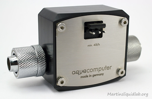
Welcome to my review of the Aqua Computer’s Flow Meter. While I have typically relied on my King Instruments analog flow meters for most of my test purposes, trying to fit a 14″ tall flow meter into your case isn’t very practical. For computers we need something smaller in size that can send an electronic signal to be processed digitally. Aqua Computers has taken a popular and high quality Digmesa sensor and fabricated a new water cooling specific housing and flow chamber for it.  We all like our G1/4 fittings and like a clean look which is the transformation that was done.

I would like to thank Shoggy from Aqua Computer for this review sample that was included for Aquaero review, thanks!

Benefits

While flow meters are not a necessary part of a water cooling loop, and they do add restriction, they also provide some information that can be used in a few different ways:

Clean Health Indicator – The tubes and blocks in your system are like veins and arteries in your body and can plug due to a variety of reasons.  Plasticizers, flux, corrosion, and sedimentation of chemicals or some dyes can all be contributing chloresteral if you will.  If you plan to keep the same loop operational for longer than 3-6 months, a precision flow meter can be a great piece of before and after information on yoru system and give you that indication that all is well without tearing everything down.  Consider it a blood pressure cuff for your water cooling system.

Emergency Shut Down – In the event that a pump fails to start, quit, or begin failing..a flow meter is one way to monitor that and shut down a system due to flow rates being too low.  I have seen at least one DDC pump loose part of it’s circuitry yet it still operated.

Complex Pump Setups & Parallel Loops – I have seen people connect up bay reservoirs incorrectly with two pumps in series such that only one was actually doing work.  Both pumps were moving and water was moving in the reservoir, but they had no idea that allowing the reservoirs to be shared essentially eliminated all work by the first pump(no pressure differential).  People are also beginning to experiment with parallel loop systems which can be an advantage but much more tricky to design properly when most parts out there don’t include basic restriction pressure drop info.  While not likely, it is possible to build a parallel system that could be a pretty bad idea if the restriction levels are too unbalance.  In parallel it is also possible to completely block one path of flow and not know it. Flow meters would again provide confirmation that things are operating as intended and continue that way.

Testing/Tinkering – This is of coarse why I like them.  While flow rate effects are generally small, I consider it taboo to test or review something thermally without also comparing restriction in some form or another.  Even if it’s not for comparison and just for information, a meter completes the package of information that is easily collected for the end user to have and think about.

I have used flow meters in the past for most of my testing work and have also used them for a couple of long term loops that I ran for over two years without cleaning, so I also see the health indicator being a value for me as I typically do like to push maintenance intervals to their maximum and generally only tear things down when upgrading.

Specification:

  • Digmesa Impeller & Sensor
  • Flow rate range: 0.67-10 l/min (LPM) / 0.18 – 2.64 GPM
  • Tolerance ± 2.0%
  • Poll value: 169 impulses per liter (Small ID Fittings)
  • Supply voltage: DC 5V 5-13 mA
  • Input-output threads: G 1/4 BSP nozzles
  • Materials used: plastic, stainless steel
  • Internals Accessible For Cleaning
  • Large 3 pin connector (larger than normal fan connector)
The specifications look promising in both flow rate sensitivity as well as voltage since an ordinary PC power supply also has 5VDC.

Plug and Play Compatibility:

If you just want to plug in the unit and have speed data converted to flow values, using an AC cable and one of the following will do that for you:
  • aquaero 5 XT / PRO / LT
  • aquaero 4.00 USB Fan-Controller
  • aquaero LT 4.00 USB Fan-Controller
  • aquaero 3.07 USB Fan-Controller
  • aquaero LT 3.07 USB Fan-Controller
  • poweradjust USB
  • poweradjust USB Version LT
  • aquastream XT USB Ultra-Version
  • aquaduct 240 Pro mark III
  • aquaduct 360 eco+
Both specifications and compatibility are good. We’ll take a closer look at the package you get next.

Welcome to my review of the Aquaero 5 XT controller. While there are many manual fan controllers out there and some software controlled options, few take the features and control as far as the Aquaero 5.  This is not the first iteration of the aquaero, it’s been many years in development through previous generations, so quite a history(since 2004) behind it.  While I have done some testing on the aquastream XT here, this is my first look at a controller as advanced as the aquaero XT 5 and it is without a doubt the most feature rich and most highly configurable controller out there.  Calling it a fan controller really doesn’t do the product justice as it is so much more and really acts as a mini computer to monitor and control your entire computer cooling system.

Before getting started, I’d like to thank Shoggy from Aqua-comuter.de for supplying this review sample. Thanks!

The product I’m reviewing is the top model aquaero XT with IR remote as you see above but there are several model options and many accessories to chose from that I’ll go into later.

GENERAL CONCEPT

Aqua-computers called it the “Aquaero” because it serves to integrate controls for and between water and air and I think that pretty fitting.While it does control fans,  it also does much more to act as the brains and control behind both a normal PC and also HTPC with all the IR connection features and ability to control other IR devices through the Aquaero 5. I basically gives you the ability to monitor, adjust, and dynamically control pretty much anything air, water, and light related.  Since I’m a visual person, I created this simplified diagram to show the various communications that may occur depending on the setup.

A big part of my intent of this guide/review is to emphasize on the “Guide” portion by learning how to use the controller and sharing what I’ve learned.

FEATURES & SPECIFICATIONS

General
  • Processor – 32bit, 48MHz with Watchdog functions
  • Flash Memory (140,000)
  • 148mm wide x 42mm tall x 62mm deep
  • Built programmable buzzer for alarm and key notes
  • Standby power via USB or 5V standby connector
  • Automatically determines which sensors are present and lists in menus
  • Automatically adjusts menus to custom renamed sensor values

LCD (XT and Pro models)

  • Backlight LCD
  • 256 x 64 resolution, 20 fps
  • Black and white (reversible & adjustible)
  • Configure menus and up to 32 customizable information pages (scrolling)

Communication/Navigation

  • Native USB 2.0 Interface to PC (no need for special drivers)
  • 1x aquabus low speed interface  (multiswitch or tubemeter)
  • 1x aquabus high speed interface (aquastream xt or poweradjust 2)
  • Universal infrared receiver (Pro or XT models)
  • Device buttons – XT=3 capacitive navigation, 4 menu/programmable, Pro=3 mechanical navigation, LT-none
  • Remote Control “Aquaremote” (XT included) optional for “Pro”
  • External IR transmitter output expandable to control other devices
  • Remote control may also be switch to control the computer (minimal mouse/keyboard control)
Fan Channel Output
  • 4x dedicated fan channels (expandable to 10 via up to 6ea poweradjusts)
  • PWM free analog DC voltage to prevent noise capable
  • Channel #2 may be converted to flow sensor
  • Channel #4 may be used to control 4 pin PWM fans/pumps
  • Max Current @12V= 1.65A/channel, max total 5A (Heat Limited)
  • Min & Max Power Setting
  • Min & Max RPM Setting
  • Startboost functions (Improves low speed startup)
  • Programmable Fuse function (1000mA)
  • Fan channels could also be used to feed pumps withing current limits.
Other Channel Outputs
  • 1X 3 pin Relay – 12V, 1A may be used for emergency shut down or other uses
  • 2x 2 pin PWM – 12V, 1A modulated at 15 kHz.  May be used for lighting.
  • 1X RGB-LED 4 pin output – up to three single color LEDs or one RGB module. 20mA, 3-4V.  Resistor built in AQ5.
  • 1X “Tacho” signal generator for Alarm functions to motherboard.
Temperature sensors external
  • 8x analog sensors ports (expandable to 40) 10kOhm NTC
  • 4x sofware sensors
  • 4x virtual sensors (Min, Mas, Delta, Abs. Delta)
  • Renaming of sensors
  • Calibration of analog sensors by offset
Temperature sensors internal (built in)
  • 1x aquaero cpu sensor
  • 4x fan amp sensors
Flow sensors external
  • 1x dedicated port
  • 2x ports if using fan port #2 as flow sensor
  • Default calibration values for AC sensor
  • Custom calibration in pulses per liter in 1 pulse increments
Monitoring
  • Fans – RPM, %, Voltage, Current
  • Temperature Sensors –  Degrees C/F/K
  • AquastreamXT Pump – Speed in Hz, Current, RPM, Voltage
  • Fill Level
  • Power Consumption using flow rate and temperature differential values
  • Logging and programmable charting functions
Controls
  • May program controls of Fans and RGB-LED
  • 4x Curve controllers – 16 point programmable curves targeting temp sensors
  • 8x Target value controllers – Programmable PID targeting control
  • 16X Two point controllers – Simple on/off lower/upper control
  • 32X Preset value – Constant
  • 1X RGB LED controller
Alarm Functions
  • Can be triggered by Temperature, Fans, Flow, Pump, Fill level
  • A variety of programmable actions: speed signal generator, buzzer,relay trigger, profile loading, power down
Software
  • Aquasuite 2012 – Allows configuration & monitoring of the unit. Settings can be saved to unit (autonomous)
  • Aquaero 5 – Software sensor tool –  Allows reading of 4X software sensors from speedfan and other programs (must be running)
So, without a doubt the AQ5 is busting out the seams in features and really has no equivalent or competition boasting this sort of feature set.   While I’ve already hit on a few notes about the model versions in the features list, next I’ll give you a bit more detail about the model versions available and expansion options.

Controlling fans manually has been available via standard fan controllers for some time, you turn a knob up or down and it adjusts the voltage to the fan and resulting speed/noise.  There are many flavors of this all manual control type, but what if you wanted to automate this process similar to current motherboard 4 pin CPU fans such that speeds remain low(low noise) while loads are light, but they are increased when the loads increase(high noise)?  There are several options to do this, but most options typically consist of a very advanced AND expensive fan controllers.

I personally have used a few manual fan controllers.  My first was one from Thermaltake, unfortunately it didn’t take long for that fan controller to burn out.  Then I bought a sunbeam rheobus controller with four channels similar to this.  I used that fan controller for over two years and to this day it still works fine although my loads were always kept fairly light.  It was cheap, but it seemed to hold up and the only obvious difference was the heatsinks that it had.

Soo…..when I heard Sunbeam was coming out with the Rheosmart to convert PWM into analog voltage, I was instantly very interested.  When they hit the shelves at Newegg, I added it to another hardware order I had planned…after all it was only $25 shipped.  It sat in the box for a while and eventually I got around to using it and ultimately doing some testing and this review.

General Photos & Information

Specs say 30 watts per channel max

PWM IN, Fan out, Fan out, Fan out, Molex In

In general the controller looks pretty good from the front.  I do like the mesh finish for some cases and the LED lights are not overly bright like my old model.  The turning knobs however feel cheap because the socket pot flexes quite a bit, but in normal operation it should work well enough.  The PCB parts and heat sinks look ok, although the sinks were not very evenly glued in place.  For the low cost the looks and quality is ok.

Operation is fairly simple.  There is a button below each knob and an LED above each knob.  When the button is pushed in the LED turns red which means it will operate under PWM.  When it is out, the LED turns green which means the knob and manual voltage controls.

Manual control range is good, giving you the ability to control from 0V to the maximum which I found to be around 11.2-11.4V due to losses in the controller while supplying it 12.1V+-.

Setup

The controller comes with a very good manual that should help you right through the process, but I’ll attempt to at least give you an idea how things work.  There are 5 ports on the controller.  Two input and three output.

  • The 4 pin molex connector is what feeds the controller and fans coming straight from the power supply
  • The 4 pin PWM fan connector is actually serving several functions.  One is a pass-through to a pump or CPU fan, in my case I used a pump.  The second function is that it sends the PWM signal and ground to the fan controller.
  • The three out connections are simply power and ground outputs to the fans.  If you use the RPM splitter cable provided  (you only get one of these), you can also send the fan RPM signal to the motherboard.

Here is a diagram of the schematic in picture form:

So, the controller takes the PWM signal generated by the motherboard and converts it to analog voltage which any normal 3 pin fan can use to speed up and slow down.  In my long term test I used the PWM pass through to also regulate the speed of my Swiftech MCP-35X which has it’s own PWM speed controller.  This way PWM is increasing and decreasing speeds of my fans using the controller as well as my pump using it’s controller.

This is what speed fan looks like watching RPM logging:

Testing

For testing, I tried two load scenarios, one light, one heavy:

  • 2 Each Fans (Yate Loon D12SL12) = Approximately a 4 Watt Load
  • 1 Each Pump (Swiftech MCP35X) PWM unplugged = Aproximately a 20 Watt Load

Fans (Light Load) PWM vs Voltage

I have been using the unit to control four yate loon fans on my CPU loop for a couple of weeks now using PWM control with very good success, so I had high expectations the testing would go very well for the light load fans test.

Unfortunately the user manual didn’t provide any sort of correlation between PWM and voltage, so I wanted to see for myself what that would be and plot that relationship. I simply used Speedfan to regulate PWM at 5% increments and a multimeter to read voltage at the fan plug.  This is that result:

Light Fan Load scaled fairly well with PWM, not quite linear, but still a good range. Max Voltage = 11.43V

In my own long term test I have been running the fans in between about 30% to 70% which means the fans have been running between 6.5V and up to 10V.  Note that maximum voltage with this lighter load is 11.43V, and my power supply is providing roughly 12.1V.  Losses within the fan controller are responsible for this voltage loss and it is fairly typical for normal fan controllers to do this unless they have a transformer to boost voltage.

Pump (Heavy Load) PWM vs Voltage

Since the controller was rated to 30 watts, I had hoped the controller would also be capable of running a standard DDC type pump via PWM>Analog control.  If this worked, it could technically turn an ordinary DDC pump into a PWM “like” pump.  I chose to use my Swiftech MCP-35X, purposely disconnecting the pump’s PWM connector so it would function like a normal DDC pump at full speed, and instead connected the 4 pin molex connector to a 4-3pin adapter then to the fan controller to allow it to voltage control.  Previous testing indicated the pump could voltage control from about 7V to 12V fairly well (not as good as it’s own PWM controller, but still some voltage control range). I then followed the same test of turning PWM down from 100% in 5% increments and recorded the voltage:

No good, the pump was too much at 65% or lower.

Unfortunately the test didn’t go well, the pump would repeatedly quit when the PWM percentage was turned to 65%.  Max voltage at 100% PWM was 11.21V.  Min voltage at 70% PWM was 10.02V, so the range was only 1.2V.  I’m assuming there just wasn’t enough current to keep the pump running or some sort of voltage instability that caused the pump to shut down.  I’m not entirely sure, but it wasn’t something I wanted to try long term considering the range was so small.

HEAT TEST

As part of the testing, I also did a manual voltage control on both the fans as well as the pump at two voltage levels.  Using manual controls I was able to dial the pump down further, although the heatsink very quickly became hot.  With my finger I could manage to touch and hold the sinks just barely at lower 40s, but more than that is too hot to touch and hold.  I think some folks understand this, but a fan controller actually has the biggest load when the voltage is lowest or furthest from the source voltage, and that is also apparent in the heat results below:

Heat sink temp using a laser thermometer

With the lighter fans load the aluminum heat sinks kept the temperature at a reasonable lower 40s or about 16-18C higher than ambient.  The pump test however produced fairly high temperatures particularly the 8V scenario which was reaching into the mid 60s.  Perhaps that’s still within specification, but I personally wouldn’t feel comfortable running one this hot especially if you had a valuable hard drive directly above and little air flow.

Conclusion

I am very happy with the controller for my own purpose of controlling around 4 watts per channel worth of fans.  It has given me dynamic loading PWM capabilities to those fans that I would otherwise not have.  My fans now throttle via CPU temperature such that 99% of the time they are a whispery 900RPM, and when I load hard such as rendering a video, playing games, or benching..they turn up to 1300RPM. I have the controller doing my fans, and the Swiftech MCP-35X using it’s own PWM controller, both are using speedfan to regulate.  Between the fans and pump reductions, PWM dynamic loading has cut my ambient noise level from 42dbA to about 35dbA which is fairly dramatic…and I’m happy.  The controller also does allow the user to switch between PWM and manual controls via a push button, so you do have some flexibility there to use a few channels manual and others PWM. In addition the PWM connector includes a daisy chain connector so I can utilize the PWM of my pump.  The pump isn’t capable of running through the controller, but the PWM signal is split to the two components with success.

I would not however recommend this controller for use on pumps or really high fan loads if the intent is to control them via PWM.  My heavy load (approx. 20 watt) test scenario failed to keep the pump operating when PWM was lowered to 65% or lower.  Heat sink temperatures also reached 64C when run passively in an open air test which is getting really hot for my own preferences.  Having the controller buried in a case front where little airflow may be available, could lead to even higher temperatures.

Overall, a great and low cost product to give you PWM like fan control of lighter loads.  I would recommend it for 5W per channel for full control. You could probably do more, but I was only successful in my light 4W test load in making use of the full PWM conversion feature and heat was also fairly comfortable at that lighter level.

Cheers!
Martin
Welcome to another pump speed controller (CTR-SPD10), and before you pass by thinking you can get the same thing from any fan controller, take a closer look.  This little analog controller is also built with a transformer so you get slight “Overvolt” capabilities as well as undervolting.  I used these controllers in my pump noise testing because of this ability and they are really well suited to driving the PMP-400  or other DDC pumps that otherwise don’t have speed control.

I would also like to thank Tim from Koolance.com for providing this sample.  These controllers gave me the ability to complete my noise testing in complete silence (my test PSU clicks very loud when switching) Thanks!!

Specifications

The controller housing notes the range of use is 7.5V to 12.7V out at 25W max.  This is really ideal for the PMP-400 or similar fixed pump.

Photos

The unit is compact in size and could be installed in a variety of locations.  It comes with a piece of velcro as one option and also a pair of screws where you could solidly mount the face by drilling three holes (one for the control knob and two for the mounting screws).

It is just over 3″ long and about 1-3/4″ wide and just under 1″ tall.


Input is a 4 pin molex, output is a 3 pin header


The control knob is located up front and has a small phillips slot

Testing

I figured the most common use of the controller would be controlling a DDC pump such as the Koolance PMP-400 pump, so that’s what I used to test the controller.  I wanted to see what the actual voltage range was when feeding it exactly 12.0V while under load of the pump.  I also wanted to take a look at the pump performance and rpm to see what changed under this control.

Minimum Voltage As Measured to pump = 7.90V

Maximum voltage as measured to pump = 13.28V

Overall, this is a good range of voltage control for this pump with the exception of the maximum being a touch high.  I have found that the PMP-400 pump doesn’t like to start beyond 13.0V, so you will need to be careful to dial down the controller just a bit to ensure starting.  12.8V is about the maximum overvolting that I would consider, so that’s what I used in testing the pump.

I did my normal pump testing to measure dynamic head pressure (outlet – inlet) while increasing restriction and measuring flow rate as shown above.  I also adjusted the pump voltage via the Koolance CTR-SPD10 to several fixed voltage ranges to see how the performance is impacted.

Performance Pressure vs. Flow Rate Summary, up to a 15% pressure head increase

Here is a look at the RPM or speed of the pump for noise reduction.

Speed (RPM) comparison, up to a 35% RPM reduction

Conclusion

This is a great little pump controller particularly for the many pumps which are fixed in speed such as the PMP-400 or other DDC pumps.  This controller essentially gives you variable power and noise control over a pump that is otherwise fixed.  In addition it gives you the option of over-volting the pump due to it’s unique transformer.  While there are many fan controllers that could also reduce speed, this is the only option I know of that can go down to 8V and UP to 13V.  Most fan controller will have a maximum below 12.0V because of losses within the fan controller.

Pros

  • 25 watts capacity is ideal for the PMP-400
  • Over-volt (13Volts) capability can increase pump pressure head by up to 15%
  • Under-volt (8 Volts) capability can reduce pump noise for ultra silence
  • Compact size make is fairly easy to install in a variety of locations
  • Simple operation up and down

Cons

  • Maximum volts can exceed pump startup limit (user needs to reduce slightly from maximum)
  • All manual control only

Overall I am very happy with this controller, particularly for it’s unique ability to not only provide a solid 12V which most fan controllers can’t do, but also to increase it for an extra bump in performance.  I would suggest installing extra cooling on pumps that you are considering overvolting, as any sort of voltage increase will also increase heat output of the pump.

Where to Buy

Koolance

Cheers!
Martin

The Koolance CTR-SPD24 is a new 24 Volt speed controller which will take your ordinary 12V power supply and allow you feed and control a pump or fan from 10 volts to 24 Volts.  This is really exciting because previous to this, 24V or higher voltage was typically only possible with a separate dedicated power supply.  In addition, the controller is ideal in controller the new stronger PMP-450S pumps.  So unlike your typical fan controller which is either PWM or resistance based (Can only reduce voltage), this one can got both directions.

Before going too far, I would like to thank Tim from Koolance.com for supplying two of these units that I have been using for my PMP-450S performance and noise testing.  Thanks!

PHOTOS

Here are some pictures showing the box, packaging, and size of the controller:

TESTING

Minimum and maximum voltage settings

For testing I am including both the minimum and maximum photos of the PMP-450S pump under load using the controller.  I fed the controller precisely 12.0V using my test power supply, and then measure the pump voltage at the pump plug for the actual voltage provided.

Minimum Voltage = 10.14V (Note: I would suggest 11V as the minimum for the PMP-450S)

Maximum Voltage (Note: I would suggest 20V as the PMP-450S maximum)

Efficiency

To determine the efficiency of the controller I measure the amperage and voltage fed to the combined pump plus controller, then did the same for just the pump.  Using these two sets of data I was able to determine the energy lost through the controller.  Here are those results:

Efficiency Calculation

It turns out the controller is very efficient at over 89%, so the heat-sink and controller is wasting up to about 5 watts at a 48 watt consumption level.  I did also measure the heat-sink with a laser thermometer and it does get warm/hot to the touch.  I measured roughly 45C in a 25C ambient which is warm, but not that hot.  I have actually measured some pumps measuring upwards of 60C, so 45C seems to be relatively good.

What good is 24V you might ask?

It’s what the “STRONG” or PMP-450S NEEDS for full out pumping performance.  The PMP-450S with this controller will easily outperform the most powerfull PMP-450/DDC pump.  It also serves as a “Vario” feature for the PMP-450S because that pump does not come with a variable speed knob.  Basically, the PMP450S and this speed controller should go as a pair for full pump performance.  Here is how the “STRONG” compares to the PMP-400 with top, and I haven’t even completed testing with a top on it.  It is simply one of the most powerful pumps you can buy at that price point.

24Volts gives the PMP-450S it's "STRONG" performance

I also know of a few people that have 24V fans and there are other needs I’m sure.  I would not suggest the controller for the regular PMP-450 pump though as the performance gain on that pump model is fairly minimal.  The pump that needs this is the PMP-450S, she likes the extra volts!!..

I really like this controller, particularly for it’s compact size, simple analog control, and extra legs it gives to the PMP-450S model pumps.  I could see this controller also coming in handy for other 24V needs, no more need to have a  separate dedicated power supply for high voltage, this fits that need nicely at a good price.  I really could not find any faults in this controller, it’s a nice compact unit and has plenty of power for one PMP-450S.  It would even have enough power to feed two PMP-450S pumps at lower voltages/lower flow rates.  I will be using these for a variety of 24V testing needs in the future, extremely nice!!

 Update 7/27/11 Connector Photo

This is how you connect up a molex connector type pump like the PMP-450S:

Cheers!
Martin